Construction
Wind turbines
We are proposing to use up to 96 wind turbine generators that are three-bladed (similar to those pictured). These will include the following elements:
- Rotors, including blades and a hub (which connects the blades to the shaft and drive train).
- A nacelle (which houses the electrical generator, control electronics and drive system).
- Structural support, which includes a tubular steel tower on top of a foundation structure.
Wind turbines are generally constructed by installing the foundation structure followed by installation of the tower. The nacelle containing the generator is next and then the three turbine blades are installed. All wind turbine components are lifted in place from a transport vessel/barge.
The layout and design of the wind farm
The exact layout of the wind turbine generators is still being developed and would not be finalised until after the project is granted a Development Consent Order (DCO) by the Secretary of State for the Department of Energy Security and Net Zero.
Wind turbine generators will be set out in rows. In-row spacing (the space between each individual wind turbine generator in a row) will now be a minimum of 1,400 metres (or 0.87 miles). Inter-row spacing (the space between each row of wind turbine generators) will also be a minimum of 1,400 metres (or 0.87 miles).
We made this increase to 1,400 metres (from 875 metres for in-row spacing and 1,000 metres for inter-row spacing) in response to feedback from shipping operators and commercial fisheries. This increase will provide additional space for continued fishing and transit by commercial fisheries between and around the Morgan Array Area.
There may be empty spaces within the wind farm site. This may be due to certain less favourable seabed conditions or, for example, because we need to keep away from existing infrastructure.
Construction is currently planned to commence in 2026/2027. Further details about how the Morgan Offshore Wind Project: Generation Assets project is proposed to be constructed can be found in Volume 1, Chapter 3: Project Description of the Environmental Statement.
Offshore Substation Platforms (OSPs)
The OSPs will contain the equipment required to transform electricity generated by the wind turbines to a higher voltage. They may also house secondary equipment and facilities for operating, maintaining and controlling the OSP. They are likely to have one or more decks, a helicopter platform, cranes and communication antenna.
OSPs are generally constructed by installing the foundation structure, then the substation components are lifted from a transport vessel/barge onto the foundation.
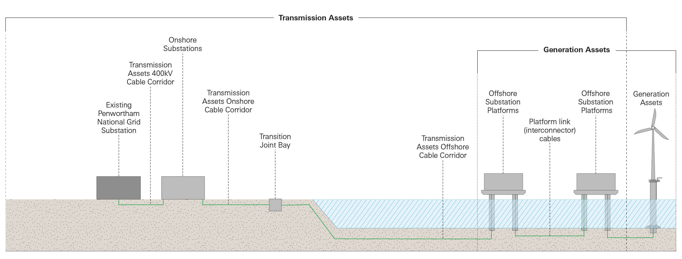
The components of the Morgan Offshore Wind Project
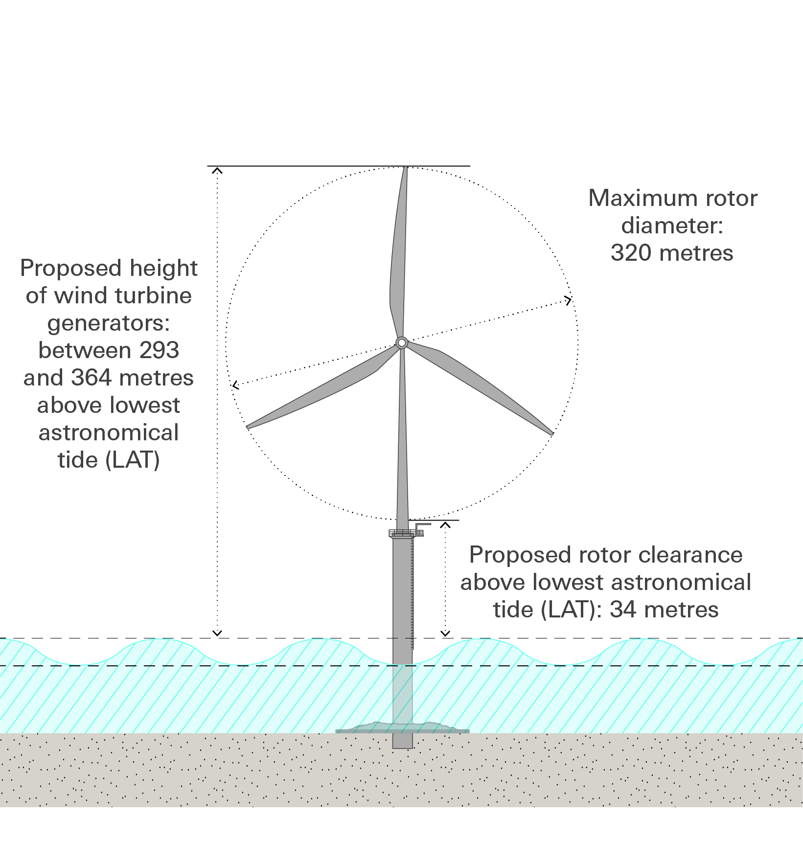
Indicative diagram of what a typical wind generator could look like. Actual design may differ.
Fast facts: Wind turbine generators
- Proposed number of wind turbine generators: up to 96
- Proposed rotor diameter: between 250 metres and 320 metres
- Proposed height of wind turbine generators: between 293 and 364 metres above the lowest astronomical tide (LAT)
- Proposed rotor clearance above lowest astronomical tide (LAT): 34 metres
Fast facts: Offshore substation platforms (OSPs)
- Proposed maximum number of OSPs: 4
- Proposed maximum topside width (’topside’ meaning the main structure on top of the foundations above the sea surface): 60 metres
- Proposed maximum topside length: 80 metres
- Proposed highest point of topside (above LAT), excluding the helicopter landing pad and lightning protection: 70 metres
Fast facts: Inter-array cables
These are installed to connect individual wind turbine generators and also connect wind turbine generators to OSPs. These will be buried below the seabed wherever possible and protected with a hard-protective layer where this burial cannot be achieved.
- Proposed maximum total length of inter-array cables: 390 kilometres (242.34 miles)
- Proposed maximum width of disturbance due to installation and burying of inter-array cables beneath the seabed: 20 metres per cable
- Target proposed depth for burying inter-array cables: 2 metres
- Maximum percentage of cable route requiring further protections: 10% (this is a ‘worst-case’ assumption)
Fast facts: Interconnector cables
Should the project require up to four OSPs, interconnector cables will be needed to connect each OSP and enable the transfer. They would also ensure that electricity transmission can continue should one cable fail. The interconnector cables will have a similar design and installation process to the inter-array cables.
- Proposed maximum number of cables: 3
- Proposed maximum length of all three cables: 60 kilometres (37.28 miles)
- Target proposed burial depth: 1 metre